What the suite covers
Porosity
Void fraction on polished sections — cast components, additive parts, thermal-spray coatings. Thresholded, reviewed, reported as %.
Area fraction · per fieldDecarburization depth
Measure total and effective decarb layers from the surface inward on etched sections, with calibrated depth callouts.
Surface → core, in µmDendrite arm spacing
Secondary DAS by intercepts across dendrite arms — the fingerprint of solidification rate in castings.
SDAS · µmLayers & coatings
Plating, galvanizing, carburized cases, weld overlays — thickness measured point by point along the interface.
Multi-point thicknessGeometry
Lines, angles, arcs, curves, polygons — snap them onto any feature and read the answer in µm or degrees.
Full toolsetAnnotations
Callouts, labels and dimension lines that live on the image and land in the report exactly as you drew them.
Report-ready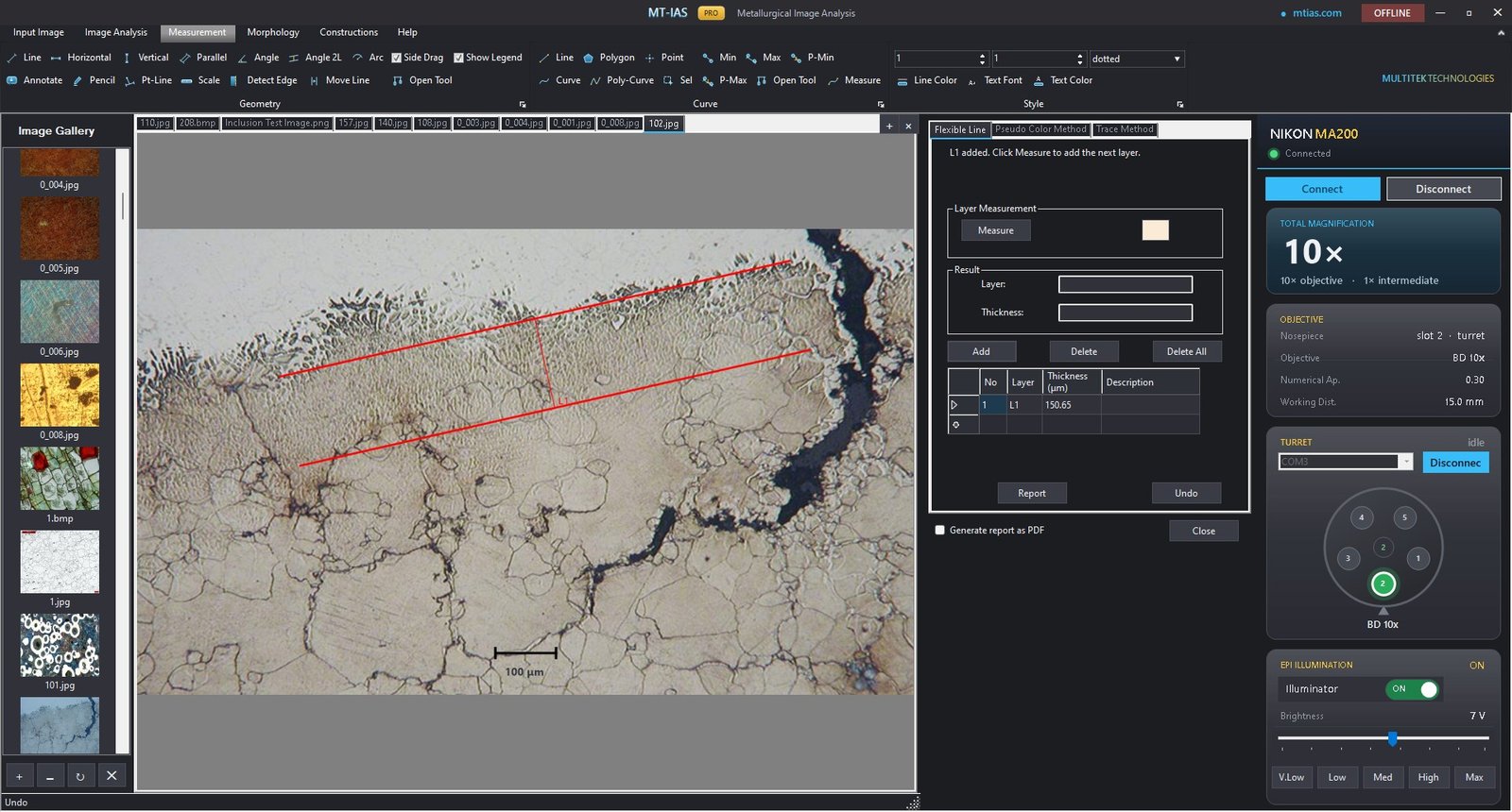
Calibration you don't have to think about
A measurement is only as good as its µm-per-pixel factor. MT-IAS Pro binds calibration to two things at once:
The objective
Each lens carries its own calibration factor. With the motorized turret integration, rotating the nosepiece — from the screen or by hand — switches the factor automatically. No stale 10× calibration under a 50× image, ever.
The camera
Calibrations are hardware-bound to the exact sensor and resolution they were made with (MultitekHDCam & NNCam). A different camera or mode can't silently reuse the wrong factor.
Common questions
What can MT-IAS Pro measure on a micrograph?
Lines, angles, arcs, curves, polygons and annotations — plus dedicated workflows for porosity, decarburization depth, dendrite arm spacing and layer/coating thickness. Everything reads out in calibrated µm.
How is accuracy maintained across objectives?
The calibration factor follows the engaged objective automatically (via the MA200 turret integration) and is bound to the exact camera hardware. The wrong factor simply can't be applied.
How do I measure decarburization depth correctly?
Etch, find the transition, measure from the surface inward at several positions — the details matter. We wrote a practical guide: Measuring decarburization depth.
Can measurements be exported?
Annotated micrographs and all measurement data export to Excel or PDF on your letterhead — the drawing you made on screen is the drawing in the report.
Measure something you already know
Bring a certified stage micrometer or a known coating to the demo — verify the calibration story yourself.